
This article is just a follow-up of drawing squares with leJOS where the problem of calibrating correctly your differential robot appeared.
So, if you recall our squares drawing robot, we needed to travel around the four legs of a square turning 90 degrees on each corner so that we ended in the initial position using nothing but the encoders available at the EV3 Large motors. That’s called odometry: the usage of data from motion sensors to estimate change in position over time.
So, in order to do our task we needed to know the wheel diameter and the wheelbase. Every one knows what the wheel diameter is ( in fact you can see the measure printed on the sides of the LEGO wheels… ) but the wheelbase is a bit more complex to define: it is the distance between the effective point where the wheels touch the ground. Unfortunately our LEGO wheels don’t cover point but a wide area, so it is unknown were the wheels in fact touch the ground, and that will surely depend of many factors like robot load, floor surface, etc…
So calibration of a differential drive robot using odometry allow us to get a more precise knowledge of where our robot is when it is moving and this will be quite helpful when running more complex techniques as localization.
Sources of error in differential robots odometry
So why the hell does the robot get the path so wrong? Well, we have two kind of errors: non-systematic errors that are those errors of position as a result of wheel slippage, uneven floor, robot bouncing against an obstacle, fast turning, etc… we can’t do anything with just odometry about them.
Systematic errors on the other hand are due to unequal wheel diameters, incorrectly aligned wheels, uncertainty about the wheelbase and the limited resolution of our encoder.
By correctly calibrating our robot we can reduce systematic errors increasing the precision for robot localization and saving battery life and CPU power.
Some basic Math about differential-drive robots
Before reading about how to calibrate, I wrote two little videos ( literally! ) about the Maths behind differential robots. It is good to refresh the idea even if it is too simple.
There are two kind of movements that we want to do:
Straight movement
Rotation movement
The brute force approach
Before explaining you the UMBMark method of robot calibration, let me explain you how you can achieve the same result with a hell less of maths and perhaps a bit less of time.
What do I need?
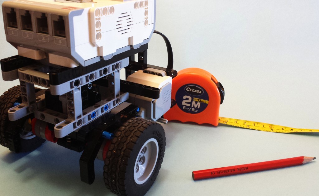
Obviously you need your differential-drive robot at hand, a measure tape and paper.

Initial differential-drive robot configuration
To begin, we are going to use the supplied wheels diameter and we will measure how big the distance between the center of the wheels is, that is going to be our wheel base.
For my robot.
Wh. Diameter = 6.24

Wheelbase = 12.8
Brute force calibration program
We are going to reuse our square path program, so we are just going to make five 1 meter-side square and at the end of each square it will wait for us to press a key.
Much like this ( Don’t worry. You can download the source code at the end of the article ).
    System.out.println("CW Run");
    brick.getAudio().systemSound(1);
    Button.waitForAnyPress();

    for(int j=0;j<5;j++) {
      for(int i=0;i<4;i++) {
        /* Move straight the squareSize centimetres */
        int degrees=(int)Math.round((squareSize/
          wheelCircunference)*360.0);
        left.rotate(degrees,true);
        right.rotate(degrees);
        left.waitComplete();

        /* Rotate on the spot */
        degrees=(int)Math.round((((wheelBase*Math.PI)/
          4.0)/wheelCircunference)*360.0);

        left.rotate(-degrees,true);
        right.rotate(degrees);
        left.waitComplete();
      }

      System.out.println("CW: "+(j+1)+"/5");
      brick.getAudio().systemSound(0);
      Button.waitForAnyPress();
    }
Get the calibration data
So we mark a point on the ground with a bit of black tape, and measure the distance to a L shaped wall next to it ( the closer the better, but allow at least 40-50cm ). Now, place the robot with extreme care over that point ( and from now on, on the very same position and orientation ).
Press any key and let the robot do one square. Now measure the distance from the ending point to the L shape wall and write it down. My advice is to give a name ( X and Y for example to each of the walls so you use the same everytime ).
Ok, make the other four patrols and write down all the results.
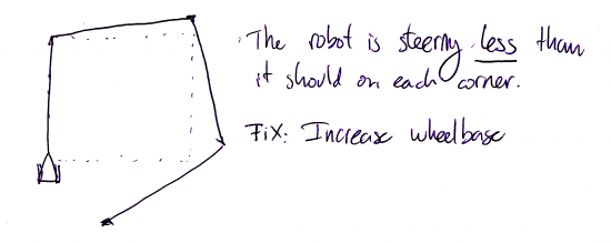
So now we need to know how big is the error, so we subtract the initial position from the finish position and that will give us a nice idea of the error. The bigger, the worse.
Xerror= Xfinish_pos - Xinitial

Yerror= Yfinish_pos - Yinitial
So unless you are incredible lucky you will end with one of these two situations.
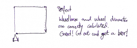
Over-steering in differential-drive robot
The robot turned more that 90ª on each of the turns so it ended steering more than it was supposed to do.
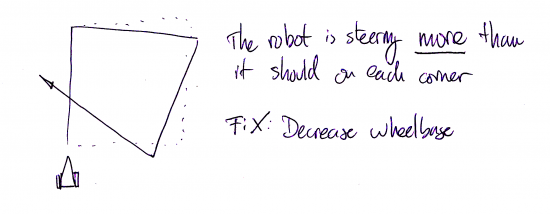
Under-steering in differential-drive robot
In this other case the robot turned less than 90 degrees on each corner.
Estimate new wheelbase
In both cases the path is wrong because of two reasons: differences on wheel diameter and error on wheelbase. The first is quite small for LEGO parts, around a 0.01% on the experiments I have done, so my advise is to just dismiss it (for simplicity) and fix wheelbase.
If you recall the Maths about how much to turn we get that
wheelbase / wheeldiameter rotations for a complete 360º turn.
So how do we write a new wheelbase for the robot? It is quite simple . If you robot over-steers on the square path, decrease the wheelbase and if it under-steered increase it. How much? The worse the bigger the change needed. I won’t go beyond 5% of the wheel base changes on a single step.
Iterate
This fine-tuning of our differential-drive robot is an iterative process so configure the new wheelbase and run it again and again until you are satisfied with the result. In the end the robot should on average land over the initial point, the existing errors, mainly due to non-systematic errors, are something you are going to need to live with until we add sensors to our robot.
The UMBMark calibration process
Perhaps you arrived here from Google looking about how to do this. On this paper, Borenstein and Feng proposes a systematic method for calibration of differential-drive robots. You can read the original paper here.
What do I need?
As with the brute-force approach you will need the differential robot and measuring tape… or three sonar sensors with a 2mm precision. [ Yep, I preferred too the measuring tape ]
Initial differential-drive robot configuration
To begin, we are going to use the supplied wheels diameter and we will measure how big the distance between the center of the wheels is, that is going to be our wheel base.
For my robot.
Wh. Diameter = 6.24

Wheelbase = 12.8
This is going to be our nominal measures… but before explaining how to do it, let me explain the Maths behind the idea on the paper, it is pretty interesting, it is simple enough and you will have a clear idea of why it isn’t optimal.
UMBMark Calibration program
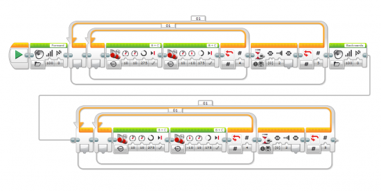
We are going to reuse our brute-force program, so we are just going to make five 1 meter-side square and at the end of each square it will wait for us to press a key. When the five squares are done we will make another five squares in the counter-clockwise direction.
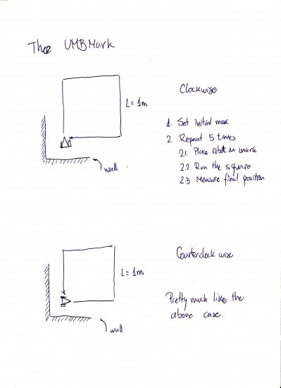
So the resulting program is pretty much like this.
    /* Initialize motors */
    left.setAcceleration(400);
    right.setAcceleration(400);

    left.setSpeed(speed);
    right.setSpeed((int)((cr/cl)*speed));

    System.out.println("CW Run");
    brick.getAudio().systemSound(1);
    Button.waitForAnyPress();

    int degrees=0;

    for(int j=0;j<1;j++) {
      for(int i=0;i<4;i++) {
        /* Move straight the squareSize centimeters */
        degrees=(int)Math.round((squareSize/
          (wheelDiameter*cl*Math.PI))*360.0);
        left.rotate(degrees,true);
        degrees=(int)Math.round((squareSize/
          (wheelDiameter*cr*Math.PI))*360.0);
        right.rotate(degrees);
        left.waitComplete();

        /* Rotate on the spot */
        degrees=(int)Math.round(wheelBase/
          (4.0*wheelDiameter*cl)*360.0);
        left.rotate(-degrees,true);
        degrees=(int)Math.round(wheelBase/
          (4.0*wheelDiameter*cr)*360.0);
        right.rotate(degrees);
        left.waitComplete();
      }

      System.out.println("CW: "+(j+1)+"/5");
      brick.getAudio().systemSound(0);
      Button.waitForAnyPress();
    }

    System.out.println("CCW Run");
    brick.getAudio().systemSound(4);
    Button.waitForAnyPress();

    for(int j=0;j<1;j++) {
      for(int i=0;i<4;i++) {
        /* Move straight the squareSize centimeters */
        degrees=(int)Math.round((squareSize/
          (wheelDiameter*cl*Math.PI))*360.0);
        left.rotate(degrees,true);
        degrees=(int)Math.round((squareSize/
          (wheelDiameter*cr*Math.PI))*360.0);
        right.rotate(degrees);
        left.waitComplete();

        /* Rotate on the spot */
        degrees=(int)Math.round(wheelBase/
          (4.0*wheelDiameter*cl)*360.0);
        left.rotate(degrees,true);
        degrees=(int)Math.round(wheelBase/
          (4.0*wheelDiameter*cr)*360.0);
        right.rotate(-degrees);
        left.waitComplete();
      }

      System.out.println("CCW: "+(j+1)+"/5");
      brick.getAudio().systemSound(0);
      Button.waitForAnyPress();
    }
  }
Get the calibration data for UMBMark
So as we did with brute-force approach, we mark a point on the ground with a bit of black tape, and measure the distance to a L shaped wall next to it ( the closer the better, but allow at least 40-50cm ). Now, place the robot with extreme care over that point ( and from now on, on the very same position and orientation ).
Press any key and let the robot do one square. Now measure the distance from the ending point to the L shape wall and write it down. My advice is to give a name ( X and Y for example to each of the walls so you use the same everytime ).
Ok, make the other four patrols and write down all the results.
Now, place the robot on the oposite direction and run the counter-clockwise part of the test. Write as before the results. ( Make sure the robot doesn’t collide with any wall or your will ruin the data ).
So now we need to know how big is the error, so we subtract the initial position from the finish position and that will give us a nice idea of the error. The bigger, the worse.
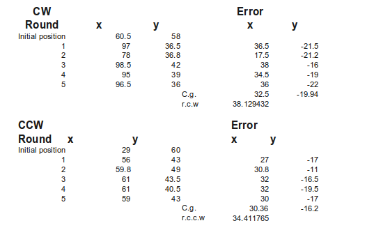
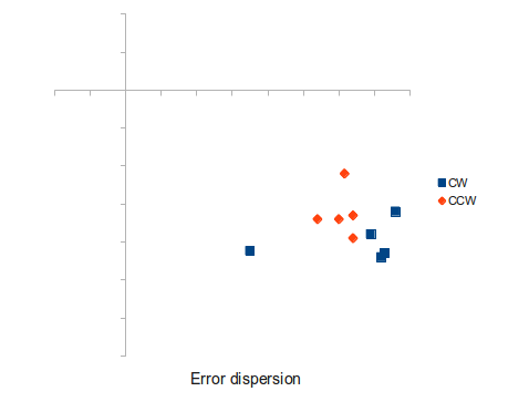
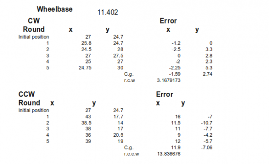
Ok, now you have the measure you should have something pretty close to this. ( You can use LibreOffice Calc to draw it ).
Ok, now we calculate the center of both sets of points CW and CCW ( It is the mean value of both x and y ).
Xcgcw = 32.5

Ycgcw = -19.94
Xcgccw = 30.36
Ycgccw = -16.2
Now we calculate β and α as explained above. For my example the results are:
αx = -0.15715

αy = 0.00935
βx = -0.00535
βy = 0.09035
Both results are in radians. On the original paper they say that you can calculate α using either X or Y values… and there is implicit there that the value is the same ( f@$% you! I lost a full day on this stupid thing. ). But it isn’t, so don’t despair, either use one of them or use the average. I used αx and βx.
So once we have β and α we can calculate the Effective Wheelbase ( Eb ) and the Effective wheel diameter (Ed). Much like this
Eb = 0.9090538881
Ed = 0.9993154352
So this means that most of the error comes from the Effective wheelbase ( what a surprise! ) and that the wheels are quite similar with the one 0.9993 smaller than the other.
Fixing your robot with Eb and Ed results
All the changes you need are done on software. We are going to fix first the most simple one, Eb.
In order to correct wheelbase we recall that we defined Eb as
Eb= Bactual/Bnominal
So we just need to alter the wheelbase as this:
wheelbase=wheelbase * Eb
Now we may want to correct the Ed. From the results I have gotten is several runs of the tests the difference between one wheel and the other is below 0.1%. You should (really) ask yourself if it is worth the time. I really think it isn’t mainly because EV3 doesn’t work with enough precision to make the change noticeable… unless you plan to run your robot on a wide open room.
Once we know Ed we can calculate a correction factor Cr and Cl for each wheel. So we correct the amount of degrees each wheel turns by multiplying the amount by Cl and Cr. Done? Well no, in fact if you fix Ed like that one wheel will stop moving sooner than the other so we need to change the speed of each wheel so both finish at the same moment.
So the amount of time each wheel is going to take to move is
degrees · Cl · vl

degrees · Cr · vr
Where vl and vr are the speed each wheel moves.
As we want both amounts to be the same…
degrees · Cl · vl = degrees · Cr · vr
vr = (Cl/Cr) * vl
Edit it and you are almost done. Now we need to change the acceleration of each motor so they both reach the maximum speed at the same time so we get a straight line.
So as we define acceleration as
a= δv/δt
We can write
t=Vr/ar

t=Vl/al
As we want that top speed is achieved at the same time for both motors…
Vl/al=Vr/ar
So we can set
al=200

ar=(vr*al)/vl
So we change the acceleration on the code and voila.
UMBMark Calibration program
Just measure your robot positions and fill the data, this Excel sheet will return you the correct Eb and Ed for your robot.
Fill only the area in grey.
[sociallocker]
![]() Download Excel sheet for Diferential-drive robot calibration using UMBMark[/sociallocker]
Download Excel sheet for Diferential-drive robot calibration using UMBMark[/sociallocker]
Bidirectional Square Path program
You can download both the leJOS version
[sociallocker]
Source Code for leJOS EV3 Differential Drive Robot Bidirectional Square patrolling
Source Code for leJOS EV3 Terminate Robot class[/sociallocker]
and the EV3 version
And this is the EV3 file.
[sociallocker]
 EV3 Source Code file
[/sociallocker]
Miguel says…
Well, you have seen both methods… and I still really prefer brute force approach.
I have run around four times the UMBMark method and every time I run it, it doesn’t beat my brute-force approach.
I decided to give it a last try with my calibrated robot so I got these results when I ran the bidirectional square path on my calibrated robot.
And these are the points
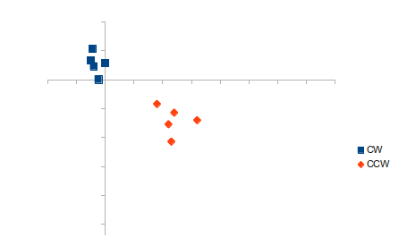
As you can see the clockwise movement is very nicely calibrated but the counter-clockwise is surprisingly wrong. I suppose this is the different wheel diameter error appearance. I re-tuned it with the params that were result of running UMBMark on the above data and the result was worse than above. It made the clockwise movement as bad as the counterclockwise movement. Not sure it is what I want…
Still… I prefer the brute force approach. But I agree it is quite hard to guess the difference between each wheel with my brute-force approach.
Miguel, this is awesome – thanks for sharing at this level of detail!
Hi,
as I mentioned before. If you change the wheel diameter, which means you need to change the motor speed, then you must also change the acceleration used. If you don’t then during the acceleration phase both motors will be the same speed (instead of one being slightly slower than the other), and the slower motor will stop accelerating before the faster one. Also remember that to get good movement (and no wheel slip), you may want to use a relatively slow acceleration and not just keep the default value. Remember that a very small error as the robot starts to move is magnified by a linear movement.
Oh and also remember that the initial alignment of the robot is very critical. You may want to use some sort of jig for this to help with the setup. In particular if you use a caster take great care over the initial alignment as it can easily throw things off. The ball baring based caster from the edu kit is much better for this!
Andy
Oh, now I see what you mean with the acceleration. I will fix and reupload the code tomorrow. I will give a try with the metallic ball… I hope it doesn’t scratch the marble or i am a dead man :D
Hi,
Nice article.
You could try using the median instead of the mean in the UMBmark method. The advantage of median is that it is not influenced by a single odd result in your test data. It might give better results.
I did the test removing the strange result ( that I am sure it is an error measuring ) and it didn’t get much better. Definitively I want to try this afternoon fixing the acceleration issue Andy told me about and replacing the caster wheel for the metallic ball… I want a zero mean error :D
I entered, copy and paste, after initial setup of a new program and a new class. I get this error message:
Multiple markers at this line
– TerminateRobot cannot be resolved to a type
– TerminateRobot cannot be resolved to a type
On this line:
TerminateRobot terminate = new TerminateRobot(brick);
What am I doing wrong?
Also, I did manage to get the previous program to work but the robot turns in a complete circle before moving forward again.
My fault.
You can download the TerminateRobot class from above or this link ( http://thetechnicgear.com/resources/TerminateRobot.java )
This class is a helper class to finish the program when you press the back button… I was quite surprised leJOS didn’t that by default.
Which one is the previous program?
How do I make this class part of Eclipse and/or part of my program?
The previous program was the “Draw a square: using motors in lejos EV3”. I was just happy the program ran. I have not had a lot of time this week to play. Hopefully I will have some time this weekend or next week.
Thank you for all your help.
Just copy it where you placed the other file.
About the program try downloading it again, I fixed an issue with acceleration that could result in a problem like the one you are talking about.
Pingback: What does happen when you run a Robot with different size wheels? ← LEGO Reviews & Videos
Pingback: What does happen when you run a Robot with different size wheels? ← LEGO Reviews & Videos
Hi,
in reply to your comment…
“This class is a helper class to finish the program when you press the back button… I was quite surprised leJOS didn’t that by default.”
leJOS does do this by default, but the keys you need are Enter+down (using just escape would mean this key is not usable by user programs) this key combination will kill your running program. But it is always better to exit your program in a clean way, stopping motors and freeing resources. Only you know the best way to do this.
Andy
I see. There are times when the program goes nuts and I really need to kill it. I will add this into the installing leJOS tutorial.
Hi,
How should I calibrate my four omni-wheeled robot? Is UMBmark method suited for odometry error corrction?
Longing to get your reply soon :)