
The easy way of learning how to built your own Line follower Robot using a PID Controller without any of the mathematical expressions that you will find on most tutorials. Code included!
The first thing you have thought about after unboxing your LEGO Mindstorms was building the first robot, and just after that you would love to make it follow lines, isn’t it?

Line following is one of the most common problems on industrial robots, and it is one of the most useful applications because it allows the robot to move from one point to another to do tasks.
There are several ways of making a Line Follower, the one that I am going to explain you about is using the Light sensor. As you know, both Mindstorms and EV3 sets come with a little light sensor that it is able to get a reading of reflected light, apart of seeing colors. On this tutorial I will explain how to do line following with just one sensor. The more sensors you have the better and faster the robot will be able to follow it.
Building the line follower robot
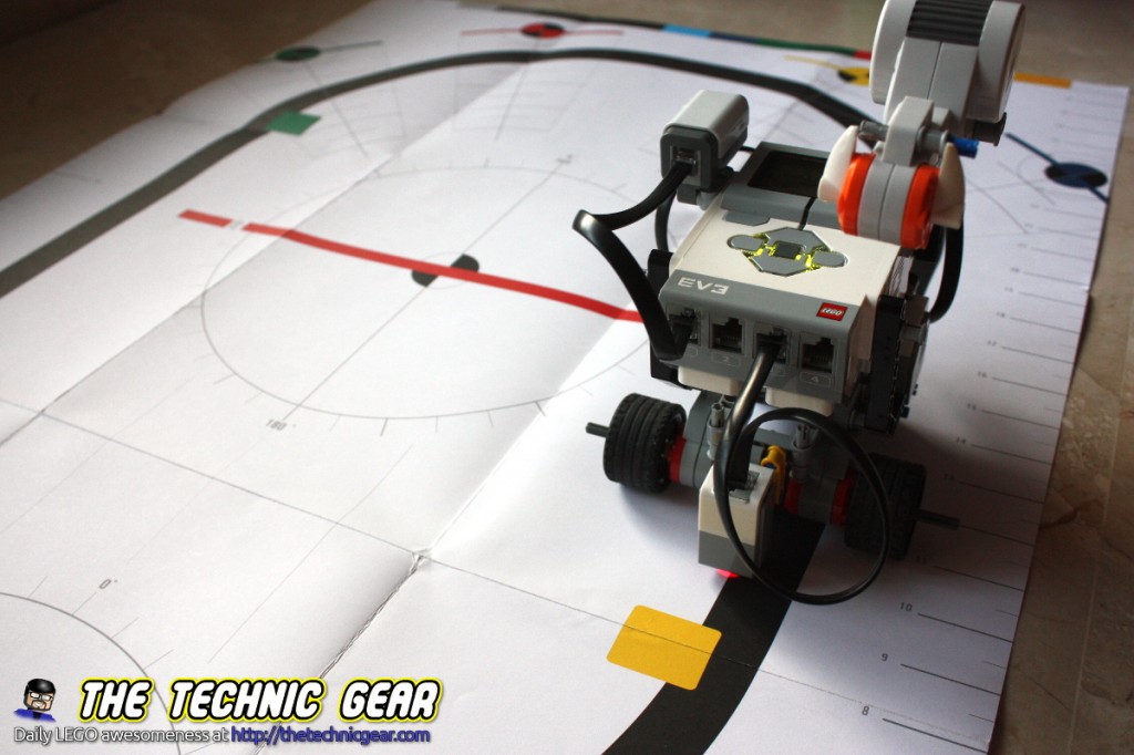
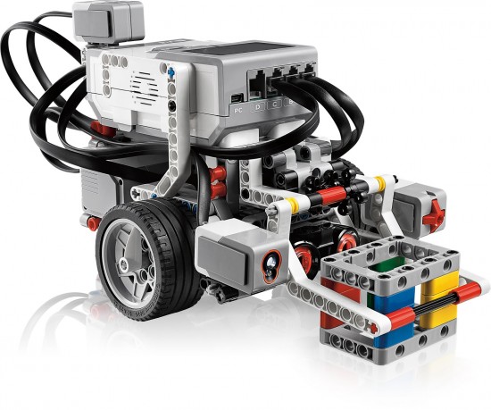
So first thing is build yourself a little robot much like Track3r, either with wheels or with tracks. You can download the instructions provided by LEGO. It is a simple construction.

Or base it on one of the LEGO Education models…
Whatever you build, just try to keep the distance between wheels to a minimum… because the bigger the distance, the harder for the robot to follow the turns on the line.
Ok, ready? Time to code. Let me explain how we get to the “best” solution with a serie of intermediate steps that will help you understand it better.
Building your playground for line following
Ok, the robot is done. But before start coding, we need the line that the robot will follow. If you happen to have the Mindstorms NXT 2.0 it has a mat with a big elipse-like line that works great for this tasks.
But if you don’t just do like me. I have used a black tape and with the finger I have sticked it to the floor creating a continuous path that the robot will follow. You don’t need a closed loop ( although it is a good idea to do it in that way ).
My floor is done of marble that it is white and brown at times and even with that it works. So it may work too on yours unless it has even less contrast than mine.
Line Following Problem definition
It is quite important to understand the line following problem first. So let’s describe the problem.
We have a thick black line on a white surface and we want our robot to move along the line following it in the fastest possible way. Right? Well, first thing that we need to understand is that we don’t want to follow the line ( wtf?! )…
No, serious, we don’t follow the line but its border in what it is called left-hand approach.
We want to follow the line where there is a 50% of white and a 50% of black.
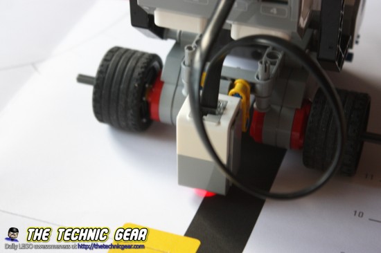
So, next step is defining what it is black and what it is white. I hope you have a clear idea of what these two colors are, but unfortunatelly your robot don’t. So the best thing you can do, before starting anything else is calibrate the robot.
Light Sensor calibration
Ok, as you know Color sensor can also work as a Light sensor, so we choose the Measure reflected light mode and we are going to store in two variables the white and black colors.
The reflected light value is just a number between 0 and 100 with the amount of light the sensor is getting back.
So the pseudocode would be
function CALIBRATE

	print "WHITE?"
	Wait for Touch Sensor to change
	white = Read Light Sensor

	print "BLACK?"
	Wait for Touch Sensor to change
	black = Read Light Sensor

done function
Do you get the idea? We add a Touch sensor to our Robot to record the light value, you can also do it using Brick buttons, as you prefer.
Here is the EV3 code that I used for it

So the idea is that you place it on the white surface, press the touch sensor, place it now on the black surface and press the touch sensor again, now we have the white and black readings and can start working.
I do it each time I start the robot but you can safely ignore it while light conditions keep stable.
Line Following with On/Off Controller
Ok, we have the robot, we have the calibration data… let’s go code. MaaaaaaahHH! Bad!
Let’s think first what we are going to do. Let’s start with the simplest possible way ( and perhaps the worse ) of doing line following.
We place the robot on the line, we get a reading if it below the middle ( black-white ) we move to one side and if it is above we move to the other side. Simple? Clever?
Let’s see again the pseudo-code
program LINE FOLLOWING

	white = 0, black = 0
	CALIBRATE()

	midpoint = ( white - black ) / 2 + black

	repeat

		value = Read Light Sensor

		if value < midpoint then
			motor B set power 50
			motor C set power 25
		else
			motor B set power 25
			motor C set power 50
		done if

	done repeat

done program
The idea is pretty simple just make one wheel turns faster than the other. Here it is how it works.
Here is the EV3 program
( You can download all the source codes on the bottom of the page )
Does it works? Well... it does... to some point. If the corner is step enough the robot will miss it and as you can see it is missing the straight line and it starts oscillating around it.
Why? Because we have only two states, so the robot is either turning left or turning right. What can we do? Exactly... add an extra state to make it go straight. So we have left, straight and right... so if we want to improve it even more we could add even more states, far left, left, a bit left, straight, a bit right, right, far right, and so on...
So why not make the turn proportional to the error, the difference between the midpoint and the value read.
Line Following with a P Controller
Do you like Maths? I don't. I have a deep understanding of them but I really can't stand the complex way of explaining simple things... so let me explain you the P Controller without any kind of mathematical notations.
If you follow the reasoning of the On/Off controller with several states you may end up thinking of a controller with infinite states, each one of them with an value proportional to the error, the difference between where we want the robot to be and where it really is.
If you want something to be proportional to a quantity you just multiply both factors so we have
how much to turn = Kp * ( midpoint - Light Sensor Reading )
Where K is a constant that helps us tune the P controller. The bigger Kp is the higher will be the turning when there is an error, but if Kp is too big you may find that the robot overreacts and that it is uncontrollable.
You can watch what happens when you change the value of Kp from 0 to 10 on this video.
So start with 1.
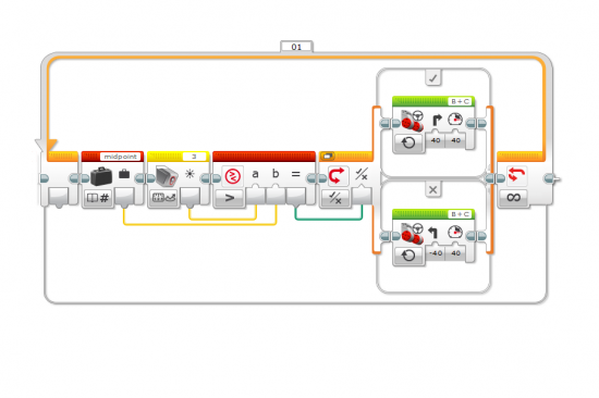
So our P-Controller would be like this pseudo code
program LINE FOLLOWING

	white = 0, black = 0
	CALIBRATE()

	midpoint = ( white - black ) / 2 + black
	kp=1;

	repeat

		value = Read Light Sensor
		correction = kp * ( midpoint - value )

		Turn B+C Motors by correction

	done repeat

done program
If you are not using the EV3 module just move one motor a value + correction and the other motor to value - correction. It is pretty much the same.
Here it is the EV3 program
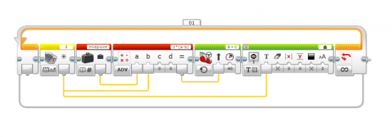
( You can download all the source codes on the bottom of the page )
Tunning the Kp parameter
Start with Kp=1 and run your robot. If the robot can't follow the turns on the line then increase Kp, if on the other hand your robot turns violently on the line, decrease the Kp value. The bigger the effect the bigger the change need on Kp. Just keep playing...
The P Controller has two problem that can be "easily" fixed with a complete PID controller: one is that it will oscilate after corrections and the other is that there is a small error that it is a direct result of the P Controller.
So let's see the complete PID controller.
Line Following with a PID Controller
A PID controller is basically a P controller with two other components, the integral part and the derivative part.
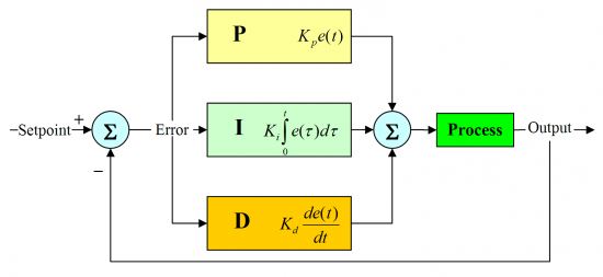
Don't be scared. Let me explain the overall idea and we move to the pseudo code.
Proportional part of the PID Controller
This is exactly the part that have just seen above.
Integral part of the PID Controller
The idea behind the integral part is that the error must tend to zero over a period of time. I will avoid you a very ugly mathematical expression explaining this... but keep in mind that as you are working inside a loop we can write
integral = integral + error
So over a number of interation we want this to be zero. Why? Because we want to correct the error, so the only way of the robot being exactly over the midpoint between black and white is that this part of the PID controller is zero too.
So our controller would be like
controller = kp * error + ki * integral
As you can imagine the only way for the integral part to be zero is to cancel the error by applying another negative error. So the robot will move from one side to the other of the midpoint in order to cancel the error and be exactly on the midpoint.
Derivative part of the PID Controller
The final part of the PID Controller is the derivative part. If we can think of the integral part as a memory of the controller, the derivative part is like an economist that watch the future and try to guess it based on past errors.
So if we know the last error and we know the actual error we can compute what the next error will be. So the derivative part of the PID controller will help the controller to correct the error faster.
One problem of the derivative part is that it is highly sensible to the noise in the controller signal ( our light detector ) so if the signal is noisy it may not estimate the correct error. And yes, light sensor is quite noisy :)
So the final PID Controller is like...
error = midpoint - value
Turn = kp * error + ki * integral + kd * derivative
Pseudocode for PID controller
So this is the pseudocode for this PID controller
program LINE FOLLOWING

	white = 0, black = 0
	CALIBRATE()

	midpoint = ( white - black ) / 2 + black
	kp = 1, ki = 1, kd = 1
	lasterror=0

	repeat

		value = Read Light Sensor
		error = midpoint - value
		integral = error + integral
		derivative = error - lasterror

		correction = kp * error + ki * integral + kd * derivative

		Turn B+C Motors by correction

		lasterror = error

	done repeat

done program
And well I won't be a true nerd if I don't show you the crazy mathematical description.
So how good does it works?
Disappointed? Keep reading...
Mindstorms EV3 PID Controller Program
So, here it is the EV3 code for the PID controller.
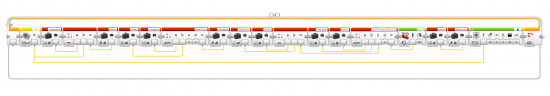
And here is the EV3 file...
[sociallocker]
Download source code for EV3 on/off controller, P-controller and PDI Controller.
 EV3 Source Code for PDI Controller
This source code is available free for you under the GNU General Public License 3 which you can read here. Basically, you are free to copy, modify, redistribute it given that you respect these freedoms on the changes you made yourself.
[/sociallocker]
Ok, got it? Now a big problem appears... what are the best values for kp, ki and kd?
How To set kp, ki and kd params in a PID controller
Well... again, I will save you all the mathematical representation of it. So after reading Wikipedia and reading about various approaches, I think the one that best suits our tasks it the heuristics approach.
So copying from Wikipedia: "If the system must remain online, one tuning method is to first set K_i and K_d values to zero. Increase the K_p until the output of the loop oscillates, then the K_p should be set to approximately half of that value for a "quarter amplitude decay" type response. Then increase K_i until any offset is corrected in sufficient time for the process. However, too much K_i will cause instability. Finally, increase K_d, if required, until the loop is acceptably quick to reach its reference after a load disturbance.
However, too much K_d will cause excessive response and overshoot. A fast PID loop tuning usually overshoots slightly to reach the setpoint more quickly; however, some systems cannot accept overshoot, in which case an over-damped closed-loop system is required, which will require a K_p setting significantly less than half that of the K_p setting that was causing oscillation."
Got it? No problem, I am here to help you.
Just set Kd and Ki to 0. Set Kp to 1 and run your robot. Does it follow the line smoothly? No, try decreasing it by a half? Can it still follow the line? No, increase it a bit... keep changing until you have the robot following a straight line without oscillations.
Then increase Ki a bit and check if it is smoother? Yes, increase a bit more... does it works worse... so a bit less...
Finally set Kd to 1 and check how fast the robot follows now the line? Too unstable, decrease it...
Keep repeating until you are happy.
How different Line following approaches compare
One video is more than enough to see it :)
Miguel says...
As a final word, you now need to know that each kind of line require a Kp, Ki and Kd params tunning to get the best of the robot.
That's all folks.
Hope you enjoyed the tutorial as much as I did. Don't miss my post about a self-balancing robot that I built using a gyro sensor I have just got from LEGO. Did you know that I run a Youtube channel with almost daily LEGO reviews and HOWTO? Please subscribe to The Technic Gear LEGO Reviews
Downloads
Download Mindstorms EV3 PID Controller.
[sociallocker]
EV3 Source Code for PID Controller
This source code is available free for you under the GNU General Public License 3 which you can read here. Basically, you are free to copy, modify, redistribute it given that you respect these freedoms on the changes you made yourself.
[/sociallocker]
Pingback: Asi se programa un robot LEGO para que siga lineas [EN]
A very informative and well-said post. Thank you for your help! Now I understand how line following works. Just so you know, there is a program that does something very similar on http://www.nxtprograms.com, but this post does a lot better job explaining how to program your own.
Thanks for your kind words.
I remember reading it when I built almost a year ago the Segway robot… I understand not enough and ended up copying the code and uploading it to the brick.
please can you explain for us the pid controller with gyro sensor , and explain for us its psedu code
miguel he means how can we intruduce the gyro sensor to the PID controller, it would be great if it works
Alright man fuck you
Pingback: The Best Ten LEGO Technic Sets ← LEGO Reviews & Videos
Pingback: Beacon tracking with LEGO Mindstorms EV3 IR Sensor ← LEGO Reviews & Videos
Thanks for an informative post. I’m new at EV3 but I have a basic math question/point. In your EV3 code for the P-Controller, you have the equation as “1*(a-b)” but I don’t understand the point of having the multiplication at all. Isn’t “1*(a-b)” exactly the same math outcome as just “a-b”? You have something similar in another post (IR beacon following) where your equation is “0.5*(a-0)”. In this second example, subtracting zero does nothing, unless I’m totally missing something?
Well, let’s see the two parts:
a) The EV3 P-controller, yes. 1*(a-b) is the same that (a-b) the point of having a 1 there is that it would be a Kp constant that in this case is 1 but on others can be 0.5, 7 or 124. So why multiply? For making clearer that there is a Kp constant with value 1.
b) On the IR Beacon, yep completely right. Again, by definition a P-controller is a controller that acts proportional to the error, and error is defined by ( reading – goal ). I want heading, the goal to be 0, so it is there to make it clearer that it is just a P-Controller.
Hope it helps.
Thanks for your guide! I have a couple of questions. How do you set up the Kp,Ki and Kd parameters in the PID Controller? I tried changing the number on this equation “0.07*a+0.3*b+1*c” but I couldn’t figure out whats happening? Also, I’m working on the WRO 2014 High School(Space Station) challenge and I want to change the line-following so it does’nt only follow the black line but also some gray areas and the green area at the starting point. Can you give me some tricks? Thank you in advance!
It is set by trial and error. It is explained in the final part of the article. I am writing a special article about how to set them up and a program to configure the robot in an easier way.
It can be tricky… one way would be to just poll again the Color sensor but this time in color mode instead of reflected light intensity. I am myself working on a similar project ( but for fun )
Do you set up the Kp,Ki and Kd parameters in this “0.07*a+0.3*b+1*c” equation? And which number is Kp, which Ki and which Kd?
Thanks for the very nice code and explanation. After looking through the programs I have a couple of questions
1) Why the motor reset block in the bang-bang controller?
2) Why the light sensor calibrate blocks on the PID controller? Does it actually give you more dynamic range in the reflected light measurement, or is it somehow just easier if the target intensity is about 50?
1) Yes, because I attached an extra motor to control the P-value. I am still writing the article.
2) Calibration will make your robot works best under any condition, you can’t assume white to be 100 and black to be 0. Just calibrate and let the robot guess them :)
great article, help me a lot.. tnks…
Pingback: The LEGO Mindstorms EV3 Laboratory Review ← LEGO Reviews & Videos
hi, I’m come from Viet Nam, can I ask you how to loading the program into the robot sd card, i just know control the robot by bluetooth and I use pascal. Can you help me?
Ummm… as far as I know you can’t use Pascal to program the EV3… You can use NXC, Java, C# or even the EV3 own language… just use any of the tools provided there on each of the languages to upload the program to the brick.
Pingback: Draw a Square: Using Motors in leJOS EV3 ← LEGO Reviews & Videos
My son (age 9) and I are new to the lego mindstorms- he built the lego mindstorms ev3 (took him 4 hours). The code written by the designer looks like greek to us both. We are attempting to get this robot to follow a black line maze. We literally spent over 13 hours today and can only get it to move backwards with a simple code we designed. Any suggestions would be greatly appreciated.
Well, in the article there are three ways of doing it… from simplest to hardest. The maths of the article are a bit hard for a 9yo but you should be able to handle them: just multiplications and divisions.
The code is available to use but you should adapt it to your robot ( or use one like mine ).
Anyway, cool thing about Mindstorms is that you are learning everyday with it.
Hi, Nice job here. We tried the code and it worked well. We now added transmission gear to the two motors making it run x4 times faster. PID fails running with same params and we can’t seem to be able to tune them with reasonable results. Running power down to 20% (returning to original speed) still is uncontrollable. Any suggestion?
Yes, I have suffered it myself when I tried my robot with bigger wheels.
The problem here is that the light sensors see a very small area so when you increase the speed the area the sensor see moves too fast when there is any kind of correction.
For faster speed you need two or more light sensors… as a rule of thumb… the more the faster. I may give it a look in a few months… when I write the linefollowing in java using leJOS.
Hallo , there is something I didn’t understand in the integral , in the EV3 program , you did intergal*0.5+eror = intergal
Yeah, because if you don’t divide the integral ( making the error smaller on each iteration ) you will have a robot that once the error is too big it will be unrecoverable and it will start spinning over itself.
Give it a try and change 0.5 by 1 and let it miss the line just a bit.
We are just making the robot to forget about errors that happened a few iterations ago and to concentrate on the actual error instead…
Thanks for your answer and also really thanks for the guide , its allot of help for me!
in the explenation you didn’t write anything about dividing it and also in the pseudo code its with no devision , just intergal = intergal + eror.
which i didn’t really understand also..
I would really appreciate if you can try explaining this to me.. say the first eror is 5 , the intergal would be 5 , then in the next time if the eror would be 3 the intergal would be 8? how is that helping to decrease the eror? I know it may be stuped questions im a teen and i would really aprpreciate you trying to help me.
Oh, it isn’t stupid at all… what you are exposing is what it is known as integral windup… the error goes up and up and up and there is no physical way for the robot to correct that error.
The idea of the integral is that using a proportional controller you would eventually reach a state of zero error. The integral just makes that state to be reached earlier by adding error after error forcing so the proportional part to correct it sooner.
http://blog.opticontrols.com/wp-content/uploads/2011/03/P-PI-PID-Responses.png
In the above image you can see that P controller gives a base error during time and I and D parts of the controller just make the controller to reach the zero error sooner.
Hope it helps.
Also , I didn’t really understand that part of intrgal.. if the eror for example would be 5 what would the intergal be?
(Sorry for my english, i’m brazilian and needed use Google Translator) Nice work guy! You really helped me alot. Before I just know how P works. With your help I understand I and D. Congratulations and thank you!
Opa, um brasileiro aqui, se quiser podermos trocar nossos contatos e trocarmos algumas ideias, o que acha?
Thanks for sharing your knowledge in EV3! as I can download the code?
because pressing on only rare signs me out
Yes, to download the source code you just need to share on a social network. Try disabling noscript or adblock
Hey a group of high school students are using the ev3 as a research project. we read the article and it has help so much. but we came up with a problem. for some reason it wont turn right. any suggestions to what could be wrong?
Hey, a group of high school students are building a line follower for a research project. We thought you article was really helpful and made us understand the while concept so much better. But we came up with a problem. Our line follower wont turn right while following the line. It will correct itself when it hits the white on the right side of the black line. But it will not correct itself right when on the left side of the black line. Do you have any idea what could be wrong?
It sounds like something wrong with an absolute value. Try printing the values of the P(ID) controller to see why it isn’t doing negative numbers…
Hey Miguel, can you answer me? I don’t understend the part of Integral. I know that integral is error+integral=integral. But on your code you multiplies integral by 0.5 and save this like be integral. What this number do in the code? Thank you to the help!
It is explained a few comments above this one. The idea is to make the PID controller “forget” about old errors and correct the actual one. Otherwise you can end up with a integral wind-up
Do you set up the Kp,Ki and Kd parameters in this “0.07*a+0.3*b+1*c” equation? And which number is Kp, which Ki and which Kd?
They are in the PID order so first is proportional, second is integral and last is derivative.
which follower is fastest one?
The one with PID Controller… but keep in mind that you have to tune the controller to get the best.
Hello, sorry for my poor english
Your article is really inspiring
I have learnt pid controller few years before and your article still teaches me a lot.
I am working a tough project about ev3 and i have couple of troublesome questions to ask:
First, the project require my light sensors place in a high position (i think is about 2.5cm above ground) and as you know, light sensor doesnt work well in this height, it only give me about 25 degree range(from white to black). Eventhough i am using two light sensors pid follower(e=s1-s2+sensorDiff), it still cannot work well(swing). I have tuned the pid constant for long time and it still doesnt work. So i want to ask do you think it ia possible to make pid controller work well under a small range of light value? If yes, what method you would suggest me to tune the pid constane?=)
Moreover, for this strange problem, i have some idea but i am not sure about the answer.
1. How does the distance between sensor and wheel(i am using the most commom big wheel) affect the performaoine of the robot?
2.for the integral part, instead of multplying the integral error by 0.xx. i reset it to zero when the error is in the range of -1 to 1. What is the difference between this two methods and, which method do you think it is more suitable to my case?
Sorry for a long comment with poor english =p hope you can reply me soon thankyou!
Let’s start with the simplest one:
2) I think the approach of multiplying for 0.xx is better that abruptly setting it to zero when it is outside of the range… but I don’t really think it is a big deal.
1) I tried myself a bigger wheels robot with the same PID controller and it didn’t worked and even it was QUITE hard to tune it for following a straight line… I think that the bigger the wheel the higher the sensor should be… but you have the problem with distance and sensor sensibility.
I want to give it another try on the future for a faster line tracking robot… but my advise is to get a decent Kp value before attempting to play with Ki and Kd.
Hope it helps.
miguel, can u tell me more about kp? i sitll no understand about the kp very well
kp is just a number that makes the robot correct the error between where it is and where it should be ( over the line ) so that the correction is PROPORTIONAL to the error… the bigger kp is the more aggressive the correction will be.
if i copy the program given for the p controller, does it work without any changes
Yes, it should as long as your robot is similar to mine… and that the sensor is close to the center of the line that joins both wheels.
Miguel, I read your article and found it very good, but I still have some questions. First of all, in which language does the codes you wrote are? It isn’t Java, right? Secondly, the EV3 Color Sensor are set to mesuere the reflected light intensity, so it can see in which part of the line it’s? And one more thing, I didn’t understand why we have to add the black to the average when setting the midpoint.
1) No, it is Mindstorms graphic language…
2) Yes, exactly. You are suppossing that black is 0 but it isn’t true most of the times… so you either do (white+black)/2 or write in a more complex but clearer (white-black)/2+black both ways is the same.
The second part I understood, but my first question was about what you called “pseudo codes “.
Oh, just something close to natural language that it is simple to understand and follow yet describes the process of designing the algorithm accurately.
How to adjust programming if the color sensor is not close to the map
Not really sure… this is the part that I have to do myself… but I would guess that as the change from black to white is now a smaller range I would reduce P until it works.
Miguel I tried but it cannot follow the straight line
Pretty cool idea, thanks for sharing.
BTW, the “easiest” way to tune a PID controller is the Ziegler-Nichols method (http://en.wikipedia.org/wiki/Ziegler%E2%80%93Nichols_method). It might be tricky to pull out with your robot though.
thanks for your article. it’s vary help me for making line follower.
I just start to build EV3, BTW I dont know how to get building instruction for line follower.
plz let me know that.
I don’t exacally get how to change the KP where in the program does this occur?
What if I don’t have a twitter/facebook or G+ account? I
Come on! Even Stephen Hawking has Facebook. Think about poor NSA who is going to spy if you don’t have a Facebook account…
I will check what I can do about it.
Nice work, it works great fro following a black or green line. How can we modify it to follow a red line considering there’s not much diff in reflected light intensity between red and white?
The sensor doesn’t read colors so red, black or blue… it is just a shade of grey… so just make a few test readings and just set black to whatever the sensor reads on red.
If on the other hand you want to detect the red color, you just need to read colors from the sensor and when the “black” line is red do something else…
How can I have a backward line follwoer
Sorry… I don’t understand the question
Miguel, thanks for this. When you are just starting to learn about robotics, these kinds of articles are really exciting.
Wonderful job! Maybe you can help me answer this question – I am using the ev3 color sensor in color sensor mode. In the reflected light mode – green is about 22 in value. the white is about 95. it can’t seem to see green in both modes. any ideas? I am trying to do line following using a green line on a white mat.
just make the correct value its opisite
Hi Muguel! Great insights. I am trying to follow your logic in a program which has only one driving motor (the large one) in rear and a medium motor (for steering) in front. I am giving the output of the PID to the medium motor (Steering motor): Is this the correct way of doing it. Let me know if my query is not very clear.
Thanks!
Avnish
Yes, but you also need to control speed, just imagine a car that take corners too fast… I would simply do speed inv proportional to the error. The bigger the slower, so the car may do corners right.
Let me know how good it works.
Thanks! By error, you mean the last error. Right?
Actually I used the calibration method as used in this video https://www.youtube.com/watch?v=BsglPxH7AXE. and later on used this calibrated value Black_4 (4 being the port number). instead of mid point.
I’m using the simple math-divide block and doing 1/error and trying to connect to the power input in the medium motor but I can’t connect this way. How should I do it?
My students have started to use leJOS and have had great success in some areas. However, the color sensors begin to flash on and off when running certain code. Have you ever had this experience?
No idea, sorry. Did you try leJOS forum? They are really friendly.
WOW…great post.
Would like to make a walking robot. Please help.
Sooo usefull! Great guide!
I have some trouble with the very narrow and sharp turns (20 degrees – like inside the “V”) – the robot goes to fast – and probably should reverse one of the wheels. Any ideas to solve this problem?
The real secret is that there is no easy universal line follower. If your case has sharp turns, just detect the situation and apply a fix for it instead of letting the PID do it.
I am facing issues when using only one driving motor (large) and a medium motor (for steering) for line following. Can anyone offer some feedback?
It should be pretty similar. Just make sure there is enough room for steering…
If you look into the image below
https://drive.google.com/file/d/0BztdPKpye8VAOTlOUHNpa0FtamM/view?usp=sharing
I am considering the maximum steering angle here as well. Since the output from the PID will be in radians (right??) and the input to the steering motor is in degrees so I am doing rad to deg conversion. The value always greater than +/-70 degrees. We want to restrict the value of angle to 30 or something so implementing a logic on these lines
If steering angle > Max steering angle
steering angle = Max steering angle
If steering angle < – Max steering angle
steering angle = – Max steering angle
Sounds good.
Hi Miguel.
I just have a RCX Lego robot. I have done a line follower but it doesn´t move in a smooth way, because I haven’t used a PID controller. Have you developed something similar for the RCX model?
Hi Tomas,
No, I haven’t developed using the RCX but the idea is the same, just that the RCX, as it is slower that NXT, will update less often the PID loop and so it will give a less smooth line following but I bet it is way better than on-off controller.
Hello, I noticed that you have a touch sensor involved in determining the reflected light values. However, in competitions such as FLL you are not allowed to touch the robot so how do you integrate this program within a string of other commands so that it will run without the touch sensor. I am fairly new at using the Lego software so it may be fairly easy to do.
Thanks
Well, in such competitions you will calibrate your robot before the competition starts. You can safely ignore the calibration as long as the light conditions are the same.
This works really great! People are very impressed when I use your P Controller on my robot, I don’t even need to learn about the PID Controller. =)
I have a question though, any reason why you use
midpoint = ( white – black ) / 2 + black
instead of
midpoint = ( white + black ) / 2
?
I can answer that. It’s because the values for white and black arent always going to be 100 and 0. So if your white is 96, and your black is 10. When you take (white – black) / 2 you get 43. But 43 is not the midpoint between 10 and 96. So you need to add the bottom one back in to get the actual midpoint which is 53.
(10 + 96)/2 = 53
that’s what @ashran83 means – it’s an easier expression to understand (at least for me) with the same result.
Anyway – great article – thanks a lot
It doesn’t matter .
(white – black) / 2 + black
= (white – black + 2*black) / 2
= (white + black) /2
Can’t download source code? The link just takes me to a page of symbols?
What OS and browser? It works for me.
Really good and informative guide, and now I really understand the PID algorithm! But I still have one question… Me and my school robotics team are trying to make a PID line follower robot, and we plan to do it with two sensors to make it faster… Can you help us to pull that off?? At least point a direction or someting.
Thanks in advance :)
Quick Question for you… We are wanting to test different Kp / Ki / Kd values in your last code.
We currently think that Kp = 1 because of current – midpoint, Ki = .5 because of integral *.5… but we cannot understand what we think is Kd is with the formula .07*a+.3*b+1*c…
We would of thought it would of been Kd something less than 1 and it would of been a+b+.25*c (say Kd was .25).
How would you tune to get .07*a+.3*b+1*c ?
Thanks in advance!
Where can I buy one of those mats for follow the line. I looked on Lego Nxt mindstorm education page and couldn’t find it.
Thankyou for teaching PID controlling
I can’t find the program source on your article how can i get the program source can you send me.;;
Miguel,
Quick question, where in your EV3 code is the KP value. do we change the .07 value to 1 to start because the turn = kp * error + ki * integral + kd * derivative and the kp value is that first number? What specific number do we change to change the kp value.
Thanks!
This helped me a lot. Even though i did not use the PID controller for following a line, but to make may robot drive straight (using gyro).It did at first spin in circles, but when i added a PID and tuned it drove in perfect lines. English is not my native language, so there might be some bad grammar.
How do I insert the PID Controller into the on off controller?
it is very good
I can’t understand each part of the source so could you please interpret the each code and send my email? actually my school h/w is making line follower robot so i really need the source and I have to present the source’s interpretation please
can you provide fritzing circuit diagram
Who is the author and writer of this article?
fucking faggot what is this shit u just wasted so much time, even a nigger could do this.
Good article… But i have a problem, how can it follow the line with 90 degree?
It will be hard due to the sharp turn. I bet you can modify the code to do it easily.
Hello,
Where could I get the test mat that you use in the video?
Greetings,
Jesus.
Pingback: Line Following Algorithms | RoboTrainers
why did you add black back in the midpoint?
Real cool implementation!
Hello and thanks for sharing
1) Don’t you have to define the midpoint somewhere in your ev3 code? Like get it as output from a calibration block, right before the loops.
2) I press the Google + block but it just leads me to post it in my Google +, which I have done about 4 times now. I also +1ed your post from your Google+ page. What else to do, still no download. (I finally made the programs manually, just asking)
Thanks again and lots of regards
Cool, can you please help me find the line follower mat ? did you buy this? where I can get one? is there a PDF file where I can print it? Thanks!
Hi! Excellent job , explaining the one sensor pid line follower . Could you maybe explain what a 4 sensor pid would be like? What would be the error in this case? And what would be the ideal placement of the sensors? One next to each other?
Very helpful